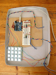
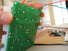
I placed the silicon button pad ontop of the soldered-up PCB and hooked it up according to the circuit I'd made earlier in which I had simulated button presses using hookup wire.
I twisted two cables together from eight strands of coloured wire to help with testing. I'm using a colour's position in the sequence of hues that form a rainbow as an indicator of its index position so that I can see quickly whether I'm connecting to the correct pin.
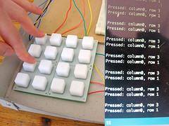
I needed to alter the code a bit to get this working. Using the orientation of the silkscreen print on the PCB's, the arduino needs to supply voltage to the rows of the sparkfun pad, and read from its columns, not the other way around.
Here's the new code:
//**************************************************************//
//  Name    : 4x4 button test                                   //
//  Author  : basementleds                                      //
//  Date    : 17 Jun, 2008                                      //
//  Version : 1.2                                               //
//  Notes   : registers pc74hct165p, pc74hct164p                 //
//****************************************************************

int pin_button_in_clock = 12;
int pin_button_in_apl = 13;
int pin_button_in_data = 11;
int pin_button_in_latch = pin_button_in_apl;

int pin_button_out_clock=2;
int pin_button_out_data=3;

byte my_bit;
byte activate_rows_byte;
byte activate_rows_byte_disposable_copy;
byte pressed_columns_byte;

void setup() {
  Serial.begin(9600); //start serial
  pinMode(pin_button_in_latch, OUTPUT);
  pinMode(pin_button_in_clock, OUTPUT);
  pinMode(pin_button_in_data, INPUT);
  pinMode(pin_button_out_data, OUTPUT);
  pinMode(pin_button_out_clock, OUTPUT);
}

void loop() {
 activate_rows_byte=1;
 for (int r=7; r>-1; r--) { // for each row
   activate_rows_byte_disposable_copy=activate_rows_byte;
   for (int x=0;x<8; x++){ // for each digit of the activate rows byte
     if((activate_rows_byte_disposable_copy & 1) != 0){
       digitalWrite(pin_button_out_data,HIGH); // if the LSB is 1, activate 'current' row
     }
     else {
       digitalWrite(pin_button_out_data,LOW);
     }
     pulse_pin(pin_button_out_clock);
     activate_rows_byte_disposable_copy=activate_rows_byte_disposable_copy >> 1;
   }
   send_row_events(get_pressed_columns(),r);
   activate_rows_byte=activate_rows_byte << 1; // cue the next lsb
 }// eo each row
 delay(900);
 Serial.println(" ");
}

void send_row_events(byte active_columns_byte,int row){
   for (int e=0; e<8; e++){
     if((active_columns_byte & 1) != 0){
       print_keypress(e,row); // send index of the detected column press, and the row index
     }
     active_columns_byte=active_columns_byte >> 1;
   }
}

void print_keypress(int column,int row){
  Serial.print("Pressed: column");
  Serial.print(column);
  Serial.print(", row ");
  Serial.println(row);
}

byte get_pressed_columns(){
  pulse_pin(pin_button_in_latch); // sample the button states
  pressed_columns_byte=0; // clear the byte ready for new data
  for (int n=0; n<8; n++){
   pressed_columns_byte = pressed_columns_byte << 1 ; // shift bits to the left, making space to capture the state of the next button
   pressed_columns_byte=clear_lsb(pressed_columns_byte); // make sure the new lsb is zero, to avoid surprises
   my_bit = digitalRead(pin_button_in_data); // store the current Q7 value from the button register in my_bit
   pressed_columns_byte = pressed_columns_byte | my_bit; // OR pressed_rows_byte with the new bit to add it to the lsb
   pulse_pin(pin_button_in_clock); // cue the next bit slot for reading
  }
  return(pressed_columns_byte);
}

// Set a pin to low, then high
void pulse_pin(int pin_number){
 digitalWrite(pin_number,LOW);
 digitalWrite(pin_number,HIGH);
}

// Clear the least significant bit
byte clear_lsb(byte byte_to_clear){
  return(byte_to_clear & 0xfe);  // AND the byte with 11111110 to be sure that the LSB is zero
}

2 comments:
man !
it's a great blog.
thank you so much for sharing all this.
i come nearly everyday to see how it's turning on.
nice blog indeed
I just began to study the buttons part for my 8x8 rgb monome-clone arduino-based project.
precisely, the 164 & 165.
thanks for your blog :)
Post a Comment