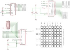
After many hours of fiddling, I found a way to wire my breadboard so that it works with the bricktable arduino code. Here's how the wiring looks for the version I have at the moment, which seems to be working correctly with the monometest patch.
Main changes since last time: the resistors attached to the 165 are now acting as pull-up resistors rather than pull-down ones. The orientation of the PCB matrix has changed, the 'top' is now the the side with the SWITCH, RED, BLUE, GREEN labels. And the 'left' is the side with the labels LED-GND and SWT-GND. Also, the 164 and 165 have 'swapped places' with respect to how they were connected to the PCB matrix.

1 comment:
do i have to turn around the diodes for the buttons, when i do it that way?
when i use the 164 for the rows (GND) there cant go anything through the diodes, when connecting it the way printed to the pcb.
am i right or do i miss something?
actually i have to use the 164 for the cols, to get it working.
Post a Comment