Friday, July 25, 2008

MachineCollective Enclosure

MachineCollective enclosure (beta)

Xndr from Machine Collective is supplying a very nice enclosure for the project. (80 EUR). This projects also acts as a kind of beta test for his sparkfun monome enclosure parts.

MachineCollective enclosure (beta)

MachineCollective enclosure (beta)

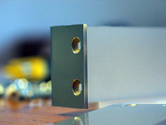
An ingenious, almost seamless aluminium side panel with nicely rounded corners.

MachineCollective enclosure (beta)

MachineCollective enclosure (beta)

MachineCollective enclosure (beta)

MachineCollective enclosure (beta)

MachineCollective enclosure (beta)

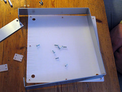
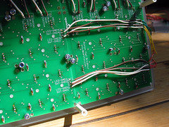
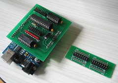
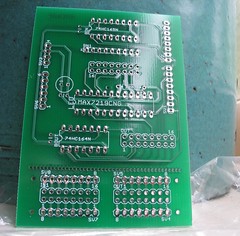
Here's the inner base panel. Notice that the shield does not sit on the arduino anymore (to keep the height of the unit to a minimum). Instead the two are connected with wires soldered to header pins. The shield is clamped in place by a few cleverly cut pieces of plastic tightened down with screws.

MachineCollective enclosure (beta)

Also, It turns out that I needn't have removed the 'break off' part of the shield. Now I have the problem of how to secure this loose piece to the base of the enclosure.

Wednesday, July 16, 2008

Soldering the Shield

Arduino Shield
Arduino Shield
Arduino Shield
Arduino Shield

I used blobs of blue-tac to hold the components with short legs in place while i soldered the first legs (choosing legs that were furthest from where the blue-tac was to avoid it heating up too much). Once the components where secured with solder, I removed the blue-tac and soldered the remaining legs.

Tuesday, July 15, 2008

Arduino Shield

Custom PCB
Custom PCB
Custom PCB
Today the Arduino shield PCB arrived. I ordered it as part of a group buy organised through the monome.org forum. Unsped created this design for his Vanome project.

In case this isn't making much sense to you: an Arduino shield is a specially designed PCB that slots ontop of an Arduino via pins that are aligned with the Arduino's sockets.

Using a correctly designed PCB means that you don't need to deal with a tangle of wires (the way my breadboard looks at the moment) because the wiring is translated to neat little copper traces on the surfaces of the board. This means that soldering is easier, that there are fewer joints that can go wrong, and that the whole thing takes up less space and can be housed in a smaller enclosure.

Eagle is a software for designing PCBs like this one. There's is a free version that can be used to design boards of limited size. There are a few good tutorials on line for getting started with Eagle. I used the free version of Eagle to create the schematics that I published in this blog. Schematics created in Eagle can be exported as specially formatted files (Gerber files) that a PCB manufacturing company can use to create small runs of circuit boards for your projects. This board was manufactured by 4pcb.com.

Update: I removed the 'break off' strip of this PCB, but with hindsight I shouldn't have!

Monday, July 14, 2008

Schematic for bricktable code

Schematic for bricktable code

After many hours of fiddling, I found a way to wire my breadboard so that it works with the bricktable arduino code. Here's how the wiring looks for the version I have at the moment, which seems to be working correctly with the monometest patch.

Main changes since last time: the resistors attached to the 165 are now acting as pull-up resistors rather than pull-down ones. The orientation of the PCB matrix has changed, the 'top' is now the the side with the SWITCH, RED, BLUE, GREEN labels. And the 'left' is the side with the labels LED-GND and SWT-GND. Also, the 164 and 165 have 'swapped places' with respect to how they were connected to the PCB matrix.

Tuesday, July 8, 2008

Button Press Bug

Button Press Bug
Here's an illustration of the problem I'm currently having while trying to get my breadboard working with the bricktable code.

If no buttons are pressed in a column, the entire column acts as though it is being pressed. When one button is pressed in a column, that button correctly registers as being pressed, and the others in the same column go unpressed. When two buttons in a column are pressed simultaneously, neither is registered as being pressed (the whole column goes unpressed).

Here's how I currently have the matrix rows and columns wired to the ICs. (NB. I switched to the bricktable coordinates so 0,0 is now the top-left button, it used to be the bottom-left one)


Matrix RowMAX pin164 pin
r0DIG 7Q0
r1DIG 6Q1
r2DIG 5Q2
r3DIG 4Q3
r4DIG 3Q4
r5DIG 2Q5
r6DIG 1Q6
r7DIG 0Q7


Matrix ColumnMAX pin165 pin
c0SEG GD7
c1SEG FD6
c2SEG ED5
c3SEG DD4
c4SEG CD3
c5SEG BD2
c6SEG AD1
c7SEG DPD0

Sunday, July 6, 2008

Progress

Misc monome stuff
The company I bought the LEDs from graciously sent me 70 replacement pieces after i'd explained to them that the previous batch included two different colours.

Unsoldering the unwanted LEDs was much harder than soldering them in. The sparkfun PCBs are now a battlefield of scorch marks. I added the new lights and they all seem to be working.

I added capacitors to the breadboard (one for each shift register and two for the MAX chip). Now my breadboard monome is almost working when I test it with monomeserial and monometest. I'm using the bricktable arduino code.

Something's going wrong with the button presses though. It's as though the buttons have been rotated ninety degrees anticlockwise relative to the LED positions. I'm hoping that bricktable guys will publish their schamatics soon which will help clear up this oddness.