Friday, October 17, 2008

Donate a name

Supercollider
Work on the mlr-ish SuperCollider app is going well. Mute groups are working correctly and now I'm starting to implement pattern recording. With the help of people on the sc-users mailinglist I've been able to get unit tests working, which speeds up the whole bug-catching and fixing cycle.

Supercollider
It would be handy to have a name for this clone already. I like the idea of naming it after an animal but didn't find anything suitable yet. All suggestions are welcome!

As soon as I have a version that does pattern recording, and preset saving/loading, I'll publish the code so if anyone else wants to extend it in their own way, it should be possible.

Wednesday, October 1, 2008

Monome clone running mlr clone


An mlr Clone Running on a Monome Clone from basementhum on Vimeo.

Here's a short clip showing a test of the Arduinome using an early version of the mlr-ish application i'm writing in SuperCollider.

Friday, September 26, 2008

Arduinome lives!

Arduinome

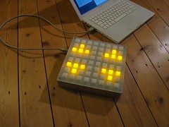
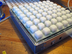
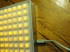
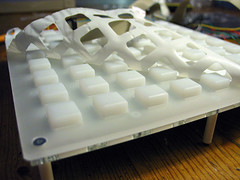
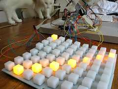
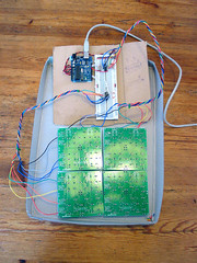
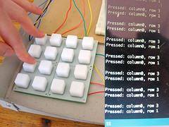
All done! xndr brought by a thicker faceplate earlier today. This means that the buttons dont stick up so far as they did before, and have a clearer, less wobbly action now.

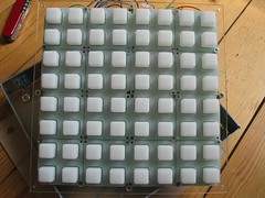
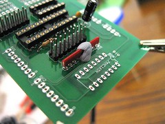
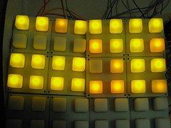
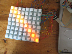
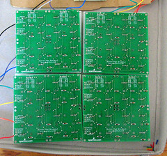
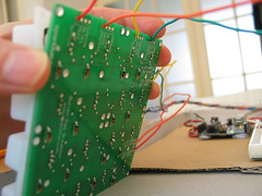
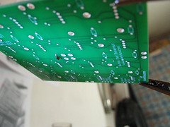
The sticking buttons are fixed too (I think); through a combination of snipping away some excess parts of silicone to stop it bunching up around the screw holes, loosening the nuts that fasten the buttons to the inner faceplate, and careful positioning of the outer faceplate to maximise the gap round each button. If you look at the large version of the following photo, you can see where the silicone has been snipped away:

Arduinome

You can find some more photos of the box in different states at my flickr photostream.

There are a few things I wish I'd known about earlier, here are a couple of the things I can remember:

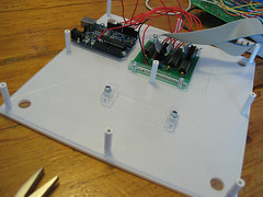
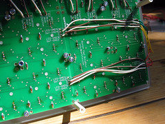
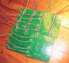
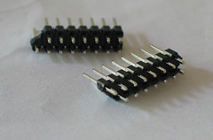
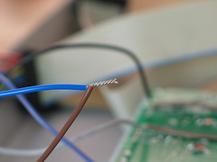
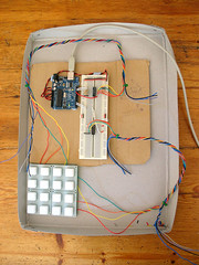
1. Solid core wire is good for breadboarding, but multicore wire would have been better for the 'real thing', since it's more flexible (easier to squash down, and out of the way) and less liable to snap. Wires snapped at solder points about ten times over the course of building this box, I came to dread opening it in case another one would break.

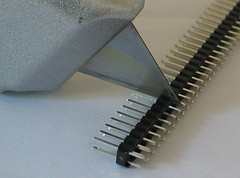
2. If you're thinking of using a Machinecollective enclosure, try to get hold of one before you start soldering, that way you'll be able to cut the wire to appropriate lengths for easier assembly.

3. The project will potentially take many hours to complete. I didn't keep a log of how long i spent on this, but its certainly much longer than I expected.

A huge thanks to Monome, for enabling people to create this kind of clone, and to everyone who's contributed their time and expertise to the Arduinome project.

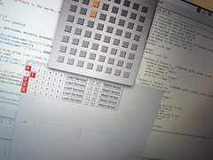
Next: I'm busy building a mlr-inspired application in SuperCollider, to use with the Arduinome. I'll post a demo, and code samples here when there's something interesting to see.

Friday, September 12, 2008

Button Action

Machinecollective Enclosure: Version 2

The new metal spacers arrived and I put the machinecollectve casing together. The box is looking great and feels sturdy generally. There are two things that i'm still hoping to fix:

1. Some of the buttons are sticking. When they're pressed they sometimes don't pop back up of their own accord.

2. Because the sparkfun buttons extend quite high above the faceplate, they often have some lateral 'wobble' when pressed. I'd like to experiment with using two stacked faceplates to steady this and get a cleaner, 'downwards only' press action.

A sidenote: I'd been putting the enclosure together the hard way all this time! Looking at Xndrs photos i noticed that he builds them from the faceplate down, instead of trying to screw things onto the bottom panel and working upwards. This makes things much easier.

Saturday, August 9, 2008

MachineCollective Enclosure, version 2

Machinecollective Enclosure: Version 2

Machinecollective Enclosure: Version 2

Machinecollective Enclosure: Version 2

Machinecollective Enclosure: Version 2

Xndr brought over new pieces for the enclosure with modified measurements and new screw holes, here are some more pictures of the enclosure in stages of assembly.

But I had some problems with the plastic spacers. Because I needed to take the box apart and put it together several times, the threads inside three of the spacers wore out. Perhaps it'll be necessary to use metal ones instead.

Meanwhile it's great to hear that the more people are busy working on the 'Arduinome' software. As well as a new version of the firmware, a custom app is being developed that will replace MonomeSerial. This app is specifically designed for use with Arduino powered monomes, and we are assured that it will bring important stability and performance improvements. Check the announcement on the Bricktable blog.

Also: a big thanks to Thomas Margolf, again I summoned his huge electronics expertise to solve a problem that turned out to have been caused by my forgetting to connect some wires [foreheadslap].

Friday, July 25, 2008

MachineCollective Enclosure

MachineCollective enclosure (beta)

Xndr from Machine Collective is supplying a very nice enclosure for the project. (80 EUR). This projects also acts as a kind of beta test for his sparkfun monome enclosure parts.

MachineCollective enclosure (beta)

MachineCollective enclosure (beta)

An ingenious, almost seamless aluminium side panel with nicely rounded corners.

MachineCollective enclosure (beta)

MachineCollective enclosure (beta)

MachineCollective enclosure (beta)

MachineCollective enclosure (beta)

MachineCollective enclosure (beta)

Here's the inner base panel. Notice that the shield does not sit on the arduino anymore (to keep the height of the unit to a minimum). Instead the two are connected with wires soldered to header pins. The shield is clamped in place by a few cleverly cut pieces of plastic tightened down with screws.

MachineCollective enclosure (beta)

Also, It turns out that I needn't have removed the 'break off' part of the shield. Now I have the problem of how to secure this loose piece to the base of the enclosure.

Wednesday, July 16, 2008

Soldering the Shield

Arduino Shield
Arduino Shield
Arduino Shield
Arduino Shield

I used blobs of blue-tac to hold the components with short legs in place while i soldered the first legs (choosing legs that were furthest from where the blue-tac was to avoid it heating up too much). Once the components where secured with solder, I removed the blue-tac and soldered the remaining legs.

Tuesday, July 15, 2008

Arduino Shield

Custom PCB
Custom PCB
Custom PCB
Today the Arduino shield PCB arrived. I ordered it as part of a group buy organised through the monome.org forum. Unsped created this design for his Vanome project.

In case this isn't making much sense to you: an Arduino shield is a specially designed PCB that slots ontop of an Arduino via pins that are aligned with the Arduino's sockets.

Using a correctly designed PCB means that you don't need to deal with a tangle of wires (the way my breadboard looks at the moment) because the wiring is translated to neat little copper traces on the surfaces of the board. This means that soldering is easier, that there are fewer joints that can go wrong, and that the whole thing takes up less space and can be housed in a smaller enclosure.

Eagle is a software for designing PCBs like this one. There's is a free version that can be used to design boards of limited size. There are a few good tutorials on line for getting started with Eagle. I used the free version of Eagle to create the schematics that I published in this blog. Schematics created in Eagle can be exported as specially formatted files (Gerber files) that a PCB manufacturing company can use to create small runs of circuit boards for your projects. This board was manufactured by 4pcb.com.

Update: I removed the 'break off' strip of this PCB, but with hindsight I shouldn't have!

Monday, July 14, 2008

Schematic for bricktable code

Schematic for bricktable code

After many hours of fiddling, I found a way to wire my breadboard so that it works with the bricktable arduino code. Here's how the wiring looks for the version I have at the moment, which seems to be working correctly with the monometest patch.

Main changes since last time: the resistors attached to the 165 are now acting as pull-up resistors rather than pull-down ones. The orientation of the PCB matrix has changed, the 'top' is now the the side with the SWITCH, RED, BLUE, GREEN labels. And the 'left' is the side with the labels LED-GND and SWT-GND. Also, the 164 and 165 have 'swapped places' with respect to how they were connected to the PCB matrix.

Tuesday, July 8, 2008

Button Press Bug

Button Press Bug
Here's an illustration of the problem I'm currently having while trying to get my breadboard working with the bricktable code.

If no buttons are pressed in a column, the entire column acts as though it is being pressed. When one button is pressed in a column, that button correctly registers as being pressed, and the others in the same column go unpressed. When two buttons in a column are pressed simultaneously, neither is registered as being pressed (the whole column goes unpressed).

Here's how I currently have the matrix rows and columns wired to the ICs. (NB. I switched to the bricktable coordinates so 0,0 is now the top-left button, it used to be the bottom-left one)


Matrix RowMAX pin164 pin
r0DIG 7Q0
r1DIG 6Q1
r2DIG 5Q2
r3DIG 4Q3
r4DIG 3Q4
r5DIG 2Q5
r6DIG 1Q6
r7DIG 0Q7


Matrix ColumnMAX pin165 pin
c0SEG GD7
c1SEG FD6
c2SEG ED5
c3SEG DD4
c4SEG CD3
c5SEG BD2
c6SEG AD1
c7SEG DPD0

Sunday, July 6, 2008

Progress

Misc monome stuff
The company I bought the LEDs from graciously sent me 70 replacement pieces after i'd explained to them that the previous batch included two different colours.

Unsoldering the unwanted LEDs was much harder than soldering them in. The sparkfun PCBs are now a battlefield of scorch marks. I added the new lights and they all seem to be working.

I added capacitors to the breadboard (one for each shift register and two for the MAX chip). Now my breadboard monome is almost working when I test it with monomeserial and monometest. I'm using the bricktable arduino code.

Something's going wrong with the button presses though. It's as though the buttons have been rotated ninety degrees anticlockwise relative to the LED positions. I'm hoping that bricktable guys will publish their schamatics soon which will help clear up this oddness.

Monday, June 30, 2008

Orange imposters

Mixed up LED package?

I'm sure about it now. Seven of the LEDs above are orange. The rest are yellow. I've asked the supplier if I can get a replacemet set of yellow ones.

Sunday, June 29, 2008

Flashing the EEPROM

In order that the MonomeSerial software 'sees' the monome clone, it's necessary to change the serial number of the arduino's EEPROM to resemble the serial number of a real monome.

I successfully followed Melka's instructions that have been posted on the bricktable blog (update: the bricktable blog instructions have been updated, you should follow those instructions rather than my version here).

You'll need access to a windows machine to complete this procedure, since the MProg software is windows only.

I'm going to paste his instructions here too (I hope that's not treading on anyone's toes), and include some of my own notes inbetween.

you have to install Mprog and the D2XX drivers from FTDI (your arduino will still work with the arduino IDE with this drivers)

MProg 3.0 > http://www.ftdichip.com/Resources/Utilities.htm
D2XX Drivers > http://www.ftdichip.com/Drivers/D2XX.htm

1/ Install both, then run Mprog

I installed the D2XX drivers on my winXP laptop first, following instructions in this PDF. This part requires you to have the arduino plugged into the PC via the usb cable. NB. while following these instructions the 'found hardware wizard' will run twice, this is normal, just point it to the directory that contains the drivers you downloaded both times.

I then installed Mprog on the same XP laptop, which was straightforward.
2/ Launch Mprog, then click on Device / Scan. You should see something like this appearing in the box down.
Code:

Number Of Blank Devices = 0
Number Of Programmed Devices = 1

3/ Click on Tools > Read and Parse. This will fill the boxes.
4/ Check the “use fixed serial number” box and change the value below.
To have your board recognized as a monome by monome serial, you have to enter something like
m40h-xxx (we used m40h-001)

I used the m40h-001 code too.
m64-xxxx
m128-xxx
m256-xxx
Choose whatever you want, I’m not sure what is different between the various IDs, for the moment I’m using m40h-001.
There is 2 protocols described on the monome site, and the 64/128/256 seems to be more complete (15 message IDs, 9 for the 40h protocol), so maybe you’d better use m256-xxx
5/ Click on File > save as
6/ Once saved, click on the flash icon (Program all existing devices, Ctrl+P).

It's the icon that looks like a lightening flash.
7/ Unplug / plug back your board from the usb port.

In my case, this meant unplugging the arduino's USB cable from my XP laptop and plugging it in to my macbook (where i have MonomeSerial installed).

8/ Run monomeserial, you should see something appear on the devices list.

You'll see the serial code you chose in the devices list (m40h-001).

Friday, June 27, 2008

Difficulty lighting a whole row

I've been adjusting the MAX test code, to gets the lights moving in different ways. While doing this I noticed that if a row is asked to light seven or eight of its LEDs at once, all the lights go out and I have to reset the arduino to get it going again. I'd like to find out why that is.
LED driver test
The button pad PCBs are all soldered up and all the components are in place in the breadboard version of the controller. To test that the MAX chip was working and wired up correctly, I uploaded this code to the arduino.

The MAX7219 has 'DIG' pins and 'SEG' pins, corresponding to the two axes of the LED matrix. The SEG pins supply voltage to the grid, and the DIG pins act as ground sinks. The SEG pins are named A to G and the eighth pin is called SEG DP. The DP pin should come first in the sequence, not last (the way I wired it first).

Once I'd corrected it, the example code gave the following pattern.

LED driver test

The difference between the two distinct colours of LED show up quite clearly (less so in the photo), that's a bit of a shame.

Tuesday, June 24, 2008

What's the best way to cleanly divide header strips?

This didn't work

The guy in my local electronics shop recommended that I just press in the notch with a knife. I tried it but wasn't able to snap them this way.

How do you break header strips apart cleanly?

So I used a chisel and hammer. Which snapped them in the correct place, but a few times the casing to one of the sides of the break was damaged, sometimes losing a pin.

So what's a reliable way to cleanly break header strips like this into the lengths that you need?

Two wires into one via

Meanwhile, at Owen's suggestion I'm twisting wires together like this as a way of attaching two of them to a single via hole in the button pad PCBs (one wire is a jumper connecting the PCB to another one, the second wire leads to one of the shift registers or the max LED driver chip).

Misc parts

Misc parts
I got hold of a few more parts I needed.

The chip in the blue box is the MAX7219CNG LED driver.

There's a long strip of paired male headers. I'll snap this into four lengths of 16 pins.

The four black plastic things with female sockets are IDC connectors to attach to two ribbon cable lengths. I messed this up with the first one I tried and broke it, this time I'll use a vice to push down the part that cuts the cable. The IDC headers will plug into the paired header pin strips, forming a removable connection from the arduino shield PCB (at least I think I'll use a shield) to the button pad.

The things with pins are IC sockets. I'm using these so that I don't have to solder the chips directly to the PCBs, and can replace them easily if necessary. There are two 16 pin sockets for the shift registers, and one 24 pin socket for the max chip.

Sunday, June 22, 2008

IDC connectors

I'm waiting around to get some parts (IC sockets, because I don't want to plug the expensive max chip directly into the breadboard for risk of bending it's legs or damaging it some other way) that will allow me to do a full breadboard test.

In the meantime here's an illuminating PDF I found. It describes how the IDC connectors work. This project will use four of them to anchor two ribbon cables to the pcbs.

Friday, June 20, 2008

Monome/arduino code online

A new section has been added to the bricktable blog which is designed to document the construction of a single colour, sparkfun+arduino monome clone, just like the one I'm building. So far there's not much information there, but they have published the arduino code for their project, which is very useful.

Since this code takes care of a bunch of things I haven't started to implement yet, like serial reading and writing, LED control and button debouncing, It's likely that I'll end up using it, or at least something derived from it.

Another blog to add to my reader.

Thursday, June 19, 2008

Four boards need linking together

The four soldered-up button pads, with the button-press-related wires hooked into the vias:

Four button pads

Four button pads

I need to add inter-pad connections like this so that all the boards can be 'reached' by the arduino:

Four button pads

I'm not sure how to arrange that, mechanically, at the moment. Can anyone see how unsped has done it in this photo? I can't quite make out how he's attaching two cables to single vias along the outside edges of the boards.

EDIT: Unsped explains that, for the edge vias which needed more than one wire attached to them, he first soldered male header pins in place, then soldered the necessary wires to those pins. Finally he covered the pins and the joints with liquid plumbers tape to prevent short-circuits. He adds that if he were to do the project again he wouldn't use header pins, but instead solder one wire pushed through the hole, and then solder the second one onto the pad created by soldering the first.

Tuesday, June 17, 2008

Testing the Sparkfun buttonpad

Button pad test

I placed the silicon button pad ontop of the soldered-up PCB and hooked it up according to the circuit I'd made earlier in which I had simulated button presses using hookup wire.

Button pad test

I twisted two cables together from eight strands of coloured wire to help with testing. I'm using a colour's position in the sequence of hues that form a rainbow as an indicator of its index position so that I can see quickly whether I'm connecting to the correct pin.

Button pad test

I needed to alter the code a bit to get this working. Using the orientation of the silkscreen print on the PCB's, the arduino needs to supply voltage to the rows of the sparkfun pad, and read from its columns, not the other way around.

Here's the new code:

//**************************************************************//
// Name : 4x4 button test //
// Author : basementleds //
// Date : 17 Jun, 2008 //
// Version : 1.2 //
// Notes : registers pc74hct165p, pc74hct164p //
//****************************************************************

int pin_button_in_clock = 12;
int pin_button_in_apl = 13;
int pin_button_in_data = 11;
int pin_button_in_latch = pin_button_in_apl;

int pin_button_out_clock=2;
int pin_button_out_data=3;

byte my_bit;
byte activate_rows_byte;
byte activate_rows_byte_disposable_copy;
byte pressed_columns_byte;

void setup() {
Serial.begin(9600); //start serial
pinMode(pin_button_in_latch, OUTPUT);
pinMode(pin_button_in_clock, OUTPUT);
pinMode(pin_button_in_data, INPUT);
pinMode(pin_button_out_data, OUTPUT);
pinMode(pin_button_out_clock, OUTPUT);
}

void loop() {
activate_rows_byte=1;
for (int r=7; r>-1; r--) { // for each row
activate_rows_byte_disposable_copy=activate_rows_byte;
for (int x=0;x<8; x++){ // for each digit of the activate rows byte
if((activate_rows_byte_disposable_copy & 1) != 0){
digitalWrite(pin_button_out_data,HIGH); // if the LSB is 1, activate 'current' row
}
else {
digitalWrite(pin_button_out_data,LOW);
}
pulse_pin(pin_button_out_clock);
activate_rows_byte_disposable_copy=activate_rows_byte_disposable_copy >> 1;
}
send_row_events(get_pressed_columns(),r);
activate_rows_byte=activate_rows_byte << 1; // cue the next lsb
}// eo each row
delay(900);
Serial.println(" ");
}

void send_row_events(byte active_columns_byte,int row){
for (int e=0; e<8; e++){
if((active_columns_byte & 1) != 0){
print_keypress(e,row); // send index of the detected column press, and the row index
}
active_columns_byte=active_columns_byte >> 1;
}
}

void print_keypress(int column,int row){
Serial.print("Pressed: column");
Serial.print(column);
Serial.print(", row ");
Serial.println(row);
}

byte get_pressed_columns(){
pulse_pin(pin_button_in_latch); // sample the button states
pressed_columns_byte=0; // clear the byte ready for new data
for (int n=0; n<8; n++){
pressed_columns_byte = pressed_columns_byte << 1 ; // shift bits to the left, making space to capture the state of the next button
pressed_columns_byte=clear_lsb(pressed_columns_byte); // make sure the new lsb is zero, to avoid surprises
my_bit = digitalRead(pin_button_in_data); // store the current Q7 value from the button register in my_bit
pressed_columns_byte = pressed_columns_byte | my_bit; // OR pressed_rows_byte with the new bit to add it to the lsb
pulse_pin(pin_button_in_clock); // cue the next bit slot for reading
}
return(pressed_columns_byte);
}

// Set a pin to low, then high
void pulse_pin(int pin_number){
digitalWrite(pin_number,LOW);
digitalWrite(pin_number,HIGH);
}

// Clear the least significant bit
byte clear_lsb(byte byte_to_clear){
return(byte_to_clear & 0xfe); // AND the byte with 11111110 to be sure that the LSB is zero
}

Soldering diodes and LEDs to the Sparkfun buttonpad PCB.

I needed to solder the components to the button pad PCBs to test further. I read a few soldering guides before beginning. This one is pretty good.

Many of the guides stress the importance of beginning with the components that would be hard to reach if others were already soldered in place. In general this means working from the middle of the pcb outwards. As I progressed, I clipped the legs off each component after it's solder had hardened, to keep things transparent.

Here's the first diode slotted in place.
Button pad test

View of the underside.
Button pad test

The first solder, it could be prettier.
Button pad test

Before I attached each LED to the board, I tested that it worked by slotting it into one of the other boards that I had hooked some wires to from my breadboard (don't forget to include a suitable resistor before the LED to prevent it from burning out).
Button pad test

Here's a view of the underside of the PCB I used to test the LEDs. It seemed to make sense to connect the anode (+ side, longer leg) of the LEDs to the BLUE via, because this places them neatly in the middle of the button area without the need to bend their little legs. While testing the LEDs I noticed that there seemed to be distinct colours of yellow in the batch that I ordered. Some LEDs shone a warm, orangy yellow and anothers a more lemony colour. I'm hoping the difference won't be pronounced enough to be disturbing, or that perhaps when the LEDs are being driven by the MAX driver, their colour will be consistent.
Button pad test

I soldered LEDs and diodes alternately, turning the PCB around as necessary while it was gripped by the pincers of the 'helping hand'. Here's the middle section almost done.
Button pad test

The finished thing.
Button pad test
Button pad test

Once it was done I used some wires from the LED testing circuit on the breadboard to touch the joints of the LEDs again to verify that they still worked. One of them didn't, I probably damaged it by applying the soldering iron for too long. Once the iron is fully heated it seems that about 2 seconds of contact with the joint before applying the solder was enough to get a good result.

I removed the dead LED using solder wick to remove the solder while pulling the plastic dome gently with pliers. I ordered 70 LEDs, so I can afford 6 of them to be wasted.