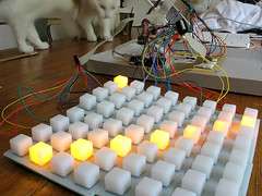
The button pad PCBs are all soldered up and all the components are in place in the breadboard version of the controller. To test that the MAX chip was working and wired up correctly, I uploaded this code to the arduino.
The MAX7219 has 'DIG' pins and 'SEG' pins, corresponding to the two axes of the LED matrix. The SEG pins supply voltage to the grid, and the DIG pins act as ground sinks. The SEG pins are named A to G and the eighth pin is called SEG DP. The DP pin should come first in the sequence, not last (the way I wired it first).
Once I'd corrected it, the example code gave the following pattern.
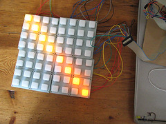
The difference between the two distinct colours of LED show up quite clearly (less so in the photo), that's a bit of a shame.

No comments:
Post a Comment