Many of the guides stress the importance of beginning with the components that would be hard to reach if others were already soldered in place. In general this means working from the middle of the pcb outwards. As I progressed, I clipped the legs off each component after it's solder had hardened, to keep things transparent.
Here's the first diode slotted in place.

View of the underside.
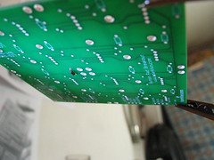
The first solder, it could be prettier.

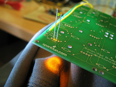
Before I attached each LED to the board, I tested that it worked by slotting it into one of the other boards that I had hooked some wires to from my breadboard (don't forget to include a suitable resistor before the LED to prevent it from burning out).
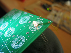
Here's a view of the underside of the PCB I used to test the LEDs. It seemed to make sense to connect the anode (+ side, longer leg) of the LEDs to the BLUE via, because this places them neatly in the middle of the button area without the need to bend their little legs. While testing the LEDs I noticed that there seemed to be distinct colours of yellow in the batch that I ordered. Some LEDs shone a warm, orangy yellow and anothers a more lemony colour. I'm hoping the difference won't be pronounced enough to be disturbing, or that perhaps when the LEDs are being driven by the MAX driver, their colour will be consistent.
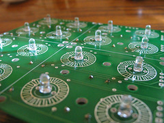
I soldered LEDs and diodes alternately, turning the PCB around as necessary while it was gripped by the pincers of the 'helping hand'. Here's the middle section almost done.

The finished thing.

Once it was done I used some wires from the LED testing circuit on the breadboard to touch the joints of the LEDs again to verify that they still worked. One of them didn't, I probably damaged it by applying the soldering iron for too long. Once the iron is fully heated it seems that about 2 seconds of contact with the joint before applying the solder was enough to get a good result.
I removed the dead LED using solder wick to remove the solder while pulling the plastic dome gently with pliers. I ordered 70 LEDs, so I can afford 6 of them to be wasted.

3 comments:
Post a Comment