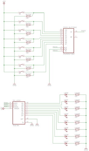
I knew that these had something to do with dealing with button presses but I wanted to understand exactly what they were doing. With the help of an electronics-savvy friend I set up an arduino circuit. In this post I'll add the schematic and the code, and in the following post I'll try to explain what the code is doing (though it's heavily annotated, so that might be redundant). Click the images to see bigger versions.
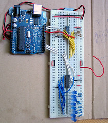
Here's how it looks on the breadboard (NB: I'm using a wire to simulate the operation of the switches).
Here's the Arduino code.
//**************************************************************//
//  Name    : shiftIn/shiftOut Example                          //
//  Author  : basementleds                                      //
//  Date    : 9 Jun, 2008                                       //
//  Version : 1.0                                               //
//  Notes   : button register pc74hct165p, led register 7JE75K  //
//****************************************************************

int pin_button_clock = 12;
int pin_button_apl = 13;
int pin_button_data = 11;
int pin_button_latch = pin_button_apl;

int pin_led_clock=2;
int pin_led_latch=3;
int pin_led_data=4;

byte my_bit;
byte button_byte;

void setup() {
  Serial.begin(9600); //start serial

  pinMode(pin_button_latch, OUTPUT);
  pinMode(pin_button_clock, OUTPUT);
  pinMode(pin_button_data, INPUT);

  pinMode(pin_led_data, OUTPUT);
  pinMode(pin_led_latch, OUTPUT);
  pinMode(pin_led_clock, OUTPUT);
}

void loop() {
  set_led_states(get_button_states());
}

byte get_button_states(){
  pulse_pin(pin_button_latch); // sample the button states
  button_byte=0; // clear the byte ready for new data
  for (int n=0; n<8; n++){
   button_byte = button_byte << 1 ; // shift bits to the left, making space to capture the state of the next button
   button_byte=clear_lsb(button_byte); // make sure the new lsb is zero, to avoid surprises
   my_bit = digitalRead(pin_button_data); // store the current Q7 value from the button register in my_bit
   button_byte = button_byte | my_bit; // OR th my_input with the new bit to add it to the lsb
   pulse_pin(pin_button_clock); // cue the next bit slot for reading
  }
  Serial.println (button_byte,BIN);
  return(button_byte);
}

void set_led_states(byte button_states){
  for (int n=0; n<8; n++) {
    if((button_states & 1) != 0) digitalWrite(pin_led_data,HIGH); // if the LSB is 1, turn the 'current' led on
     else digitalWrite(pin_led_data,LOW);
    button_states = button_states >> 1; // Shift to get a new LSB from buttonstates
    pulse_pin(pin_led_clock); // address the next bit slot
   }
  pulse_pin(pin_led_latch); // when the latch goes from low to high, the data that's been stored to the register's memory gets sent to its output pins
}

// Set a pin to low, then high
void pulse_pin(int pin_number){
 digitalWrite(pin_number,LOW);
 digitalWrite(pin_number,HIGH);
}

// Clear the least significant bit
byte clear_lsb(byte byte_to_clear){
  return(byte_to_clear & 0xfe);  // AND the byte with 11111110 to be sure that the LSB is zero
}
Here's how it should look when it's running:
Shift registers 1 from basementhum on Vimeo.

5 comments:
Update: After I swapped the LED register in this example for the PC74HCT164P, I noticed that when one of the LEDs was lit, they all glowed faintly. Not sure why.
Hey- thanks alot for this post! I am finding it really useful... keep up the great work.
Thanks for your posts! Shift registers were dificult to understand for me until I found your blog.
I have wired circuit as shown at your schema but println(button_byte) always outputs random sequence of bits. Sometimes 11010111, sometimes 11101111 and so on. Even if 74hc165 pins are not switched I still get that random sequences. Could you please tell me what I did wrong?
Sorry for my english, its not so good. I really need your help.
Same problem.
I've that random sequences.
anyone for a solution?
2TrainingMan: I solved my problem by adding 10kOm resistors to each shiftregister's pin as shown on scheme
Post a Comment