
I'm not sure I've set this up in the most sensible way, but it's working. Here's a high level account of what's going on:
- The arduino loads the parallel-out register with a byte which has just one bit turned on. The one bit corresponds to one of the channels.
- The corresponding pin of the parallel out register goes high, this provides voltage to one of the rows of the button matrix.
- The arduino pulses the latch pin of the serial out register so that it samples from the outputs of the button matrix columns
- If a button is pressed in the active row, the column of that button will be HIGH when the register samples it
- Next the arduino reads the contents of the serial output register, sending it clock pulses to access the byte one bit at a time.
- Now that the arduino 'knows' which buttons are pressed in the current column, it creates a new byte to send to the parallel out register, to active the next row in the sequence
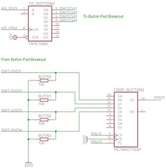
Here's how the schematic looks.
Here's a closeup of the PCB. The wires are just loosely hooked in place as an aid to understanding how the signal will flow in the future.

This is the code running on the arduino.
//**************************************************************//
//  Name    : 4x4 button test                                   //
//  Author  : basementleds                                      //
//  Date    : 13 Jun, 2008                                      //
//  Version : 1.0                                               //
//  Notes   : registers pc74hct165p, pc74hct164p                 //
//****************************************************************

int pin_button_in_clock = 12;
int pin_button_in_apl = 13;
int pin_button_in_data = 11;
int pin_button_in_latch = pin_button_in_apl;

int pin_button_out_clock=2;
int pin_button_out_data=3;

byte my_bit;
byte pressed_rows_byte;
byte column_byte;
byte column_byte_disposable_copy;

void setup() {
  Serial.begin(9600); //start serial
  pinMode(pin_button_in_latch, OUTPUT);
  pinMode(pin_button_in_clock, OUTPUT);
  pinMode(pin_button_in_data, INPUT);
  pinMode(pin_button_out_data, OUTPUT);
  pinMode(pin_button_out_clock, OUTPUT);
}

void loop() {
 column_byte=1;
 for (int c=7; c>-1; c--) { // for each column
   column_byte_disposable_copy=column_byte;
   for (int x=0;x<8; x++){
     if((column_byte_disposable_copy & 1) != 0){
       digitalWrite(pin_button_out_data,HIGH); // if the LSB is 1, turn the 'current' led on
     }
     else {
       digitalWrite(pin_button_out_data,LOW);
     }
     pulse_pin(pin_button_out_clock);
     column_byte_disposable_copy=column_byte_disposable_copy >> 1;
   }
   send_column_events(get_pressed_rows(),c);
   column_byte=column_byte << 1;
 }// eo each column
 delay(900);
 Serial.println(" ");
}

void send_column_events(byte active_rows_byte,int column){
   for (int e=0; e<8; e++){
     if((active_rows_byte & 1) != 0){
       print_keypress(column,e);
     }
     active_rows_byte=active_rows_byte >> 1;
   }
}

void print_keypress(int x,int y){
  Serial.print("Pressed: ");
  Serial.print(x);
  Serial.print(", ");
  Serial.println(y);
}

byte get_pressed_rows(){
  pulse_pin(pin_button_in_latch); // sample the button states
  pressed_rows_byte=0; // clear the byte ready for new data
  for (int n=0; n<8; n++){
   pressed_rows_byte = pressed_rows_byte << 1 ; // shift bits to the left, making space to capture the state of the next button
   pressed_rows_byte=clear_lsb(pressed_rows_byte); // make sure the new lsb is zero, to avoid surprises
   my_bit = digitalRead(pin_button_in_data); // store the current Q7 value from the button register in my_bit
   pressed_rows_byte = pressed_rows_byte | my_bit; // OR pressed_rows_byte with the new bit to add it to the lsb
   pulse_pin(pin_button_in_clock); // cue the next bit slot for reading
  }
  return(pressed_rows_byte);
}

// Set a pin to low, then high
void pulse_pin(int pin_number){
 digitalWrite(pin_number,LOW);
 digitalWrite(pin_number,HIGH);
}

// Clear the least significant bit
byte clear_lsb(byte byte_to_clear){
  return(byte_to_clear & 0xfe);  // AND the byte with 11111110 to be sure that the LSB is zero
}
Here I've simulated pressing three buttons by making connections between the input (SWITCH) and the output (SWITCH-GND) sockets. Below you see the output of the serial window in the arduino software.

Next I need to figure out how to connect these wires to the PCB in a non-permanent way so that I can test this circuit with the real buttons, and see if it's still working as expected. If anyone has any thoughts about how I could do that please post in the comments.

4 comments:
in point 5: was it meant to be the "input register" ?
regards
hi ulrich. No, serial output register is actually what I mean to say.
The circuit uses two registers; a parallel out (serial in) and a serial out (parallel in).
The serial output register samples from its parallel input pins (which come from the button matrix) and passes on that information to its output as a series of bits, one at a time. Every time it receives a clock pulse from the arduino it passes value of the 'next' bit to the serial out pin.
I hope it's clear.
The confusion might come from the fact that, from the point of view of the arduino, it also makes sense to consider the register that sources current to the matrix the 'output' register and the one that provides ground sinks to the matrix columns the 'input' register.
Of course if we switch to the matrixes 'point of view' the relationship is reversed! So i thought it would be simplest to talk about the parallel output register, and the serial output register.
hi
checked over my connections again and again, all looks good
i get ALL buttons firing regardless of what's pressed
did you ever come across this problem?
thanks
jim
Post a Comment