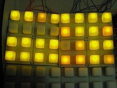
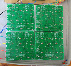
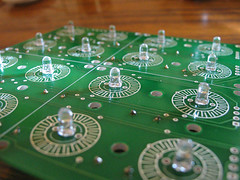
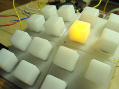
I'm sure about it now. Seven of the LEDs above are orange. The rest are yellow. I've asked the supplier if I can get a replacemet set of yellow ones.
you have to install Mprog and the D2XX drivers from FTDI (your arduino will still work with the arduino IDE with this drivers)
MProg 3.0 > http://www.ftdichip.com/Resources/Utilities.htm
D2XX Drivers > http://www.ftdichip.com/Drivers/D2XX.htm
1/ Install both, then run Mprog
2/ Launch Mprog, then click on Device / Scan. You should see something like this appearing in the box down.
Code:
Number Of Blank Devices = 0
Number Of Programmed Devices = 1
3/ Click on Tools > Read and Parse. This will fill the boxes.
4/ Check the “use fixed serial number” box and change the value below.
To have your board recognized as a monome by monome serial, you have to enter something like
m40h-xxx (we used m40h-001)
m64-xxxx
m128-xxx
m256-xxx
Choose whatever you want, I’m not sure what is different between the various IDs, for the moment I’m using m40h-001.
There is 2 protocols described on the monome site, and the 64/128/256 seems to be more complete (15 message IDs, 9 for the 40h protocol), so maybe you’d better use m256-xxx
5/ Click on File > save as
6/ Once saved, click on the flash icon (Program all existing devices, Ctrl+P).
7/ Unplug / plug back your board from the usb port.
8/ Run monomeserial, you should see something appear on the devices list.

//**************************************************************//
// Name : 4x4 button test //
// Author : basementleds //
// Date : 17 Jun, 2008 //
// Version : 1.2 //
// Notes : registers pc74hct165p, pc74hct164p //
//****************************************************************
int pin_button_in_clock = 12;
int pin_button_in_apl = 13;
int pin_button_in_data = 11;
int pin_button_in_latch = pin_button_in_apl;
int pin_button_out_clock=2;
int pin_button_out_data=3;
byte my_bit;
byte activate_rows_byte;
byte activate_rows_byte_disposable_copy;
byte pressed_columns_byte;
void setup() {
Serial.begin(9600); //start serial
pinMode(pin_button_in_latch, OUTPUT);
pinMode(pin_button_in_clock, OUTPUT);
pinMode(pin_button_in_data, INPUT);
pinMode(pin_button_out_data, OUTPUT);
pinMode(pin_button_out_clock, OUTPUT);
}
void loop() {
activate_rows_byte=1;
for (int r=7; r>-1; r--) { // for each row
activate_rows_byte_disposable_copy=activate_rows_byte;
for (int x=0;x<8; x++){ // for each digit of the activate rows byte
if((activate_rows_byte_disposable_copy & 1) != 0){
digitalWrite(pin_button_out_data,HIGH); // if the LSB is 1, activate 'current' row
}
else {
digitalWrite(pin_button_out_data,LOW);
}
pulse_pin(pin_button_out_clock);
activate_rows_byte_disposable_copy=activate_rows_byte_disposable_copy >> 1;
}
send_row_events(get_pressed_columns(),r);
activate_rows_byte=activate_rows_byte << 1; // cue the next lsb
}// eo each row
delay(900);
Serial.println(" ");
}
void send_row_events(byte active_columns_byte,int row){
for (int e=0; e<8; e++){
if((active_columns_byte & 1) != 0){
print_keypress(e,row); // send index of the detected column press, and the row index
}
active_columns_byte=active_columns_byte >> 1;
}
}
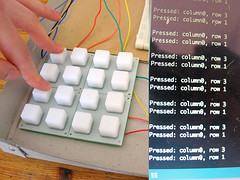
void print_keypress(int column,int row){
Serial.print("Pressed: column");
Serial.print(column);
Serial.print(", row ");
Serial.println(row);
}
byte get_pressed_columns(){
pulse_pin(pin_button_in_latch); // sample the button states
pressed_columns_byte=0; // clear the byte ready for new data
for (int n=0; n<8; n++){
pressed_columns_byte = pressed_columns_byte << 1 ; // shift bits to the left, making space to capture the state of the next button
pressed_columns_byte=clear_lsb(pressed_columns_byte); // make sure the new lsb is zero, to avoid surprises
my_bit = digitalRead(pin_button_in_data); // store the current Q7 value from the button register in my_bit
pressed_columns_byte = pressed_columns_byte | my_bit; // OR pressed_rows_byte with the new bit to add it to the lsb
pulse_pin(pin_button_in_clock); // cue the next bit slot for reading
}
return(pressed_columns_byte);
}
// Set a pin to low, then high
void pulse_pin(int pin_number){
digitalWrite(pin_number,LOW);
digitalWrite(pin_number,HIGH);
}
// Clear the least significant bit
byte clear_lsb(byte byte_to_clear){
return(byte_to_clear & 0xfe); // AND the byte with 11111110 to be sure that the LSB is zero
}


//**************************************************************//
//  Name    : 4x4 button test                                   //
//  Author  : basementleds                                      //
//  Date    : 13 Jun, 2008                                      //
//  Version : 1.0                                               //
//  Notes   : registers pc74hct165p, pc74hct164p                 //
//****************************************************************

int pin_button_in_clock = 12;
int pin_button_in_apl = 13;
int pin_button_in_data = 11;
int pin_button_in_latch = pin_button_in_apl;

int pin_button_out_clock=2;
int pin_button_out_data=3;

byte my_bit;
byte pressed_rows_byte;
byte column_byte;
byte column_byte_disposable_copy;

void setup() {
  Serial.begin(9600); //start serial
  pinMode(pin_button_in_latch, OUTPUT);
  pinMode(pin_button_in_clock, OUTPUT);
  pinMode(pin_button_in_data, INPUT);
  pinMode(pin_button_out_data, OUTPUT);
  pinMode(pin_button_out_clock, OUTPUT);
}

void loop() {
 column_byte=1;
 for (int c=7; c>-1; c--) { // for each column
   column_byte_disposable_copy=column_byte;
   for (int x=0;x<8; x++){
     if((column_byte_disposable_copy & 1) != 0){
       digitalWrite(pin_button_out_data,HIGH); // if the LSB is 1, turn the 'current' led on
     }
     else {
       digitalWrite(pin_button_out_data,LOW);
     }
     pulse_pin(pin_button_out_clock);
     column_byte_disposable_copy=column_byte_disposable_copy >> 1;
   }
   send_column_events(get_pressed_rows(),c);
   column_byte=column_byte << 1;
 }// eo each column
 delay(900);
 Serial.println(" ");
}

void send_column_events(byte active_rows_byte,int column){
   for (int e=0; e<8; e++){
     if((active_rows_byte & 1) != 0){
       print_keypress(column,e);
     }
     active_rows_byte=active_rows_byte >> 1;
   }
}

void print_keypress(int x,int y){
  Serial.print("Pressed: ");
  Serial.print(x);
  Serial.print(", ");
  Serial.println(y);
}

byte get_pressed_rows(){
  pulse_pin(pin_button_in_latch); // sample the button states
  pressed_rows_byte=0; // clear the byte ready for new data
  for (int n=0; n<8; n++){
   pressed_rows_byte = pressed_rows_byte << 1 ; // shift bits to the left, making space to capture the state of the next button
   pressed_rows_byte=clear_lsb(pressed_rows_byte); // make sure the new lsb is zero, to avoid surprises
   my_bit = digitalRead(pin_button_in_data); // store the current Q7 value from the button register in my_bit
   pressed_rows_byte = pressed_rows_byte | my_bit; // OR pressed_rows_byte with the new bit to add it to the lsb
   pulse_pin(pin_button_in_clock); // cue the next bit slot for reading
  }
  return(pressed_rows_byte);
}

// Set a pin to low, then high
void pulse_pin(int pin_number){
 digitalWrite(pin_number,LOW);
 digitalWrite(pin_number,HIGH);
}

// Clear the least significant bit
byte clear_lsb(byte byte_to_clear){
  return(byte_to_clear & 0xfe);  // AND the byte with 11111110 to be sure that the LSB is zero
}

 http://www.htvision.com/product.asp?intProdID=159
//**************************************************************//
//  Name    : shiftIn/shiftOut Example                          //
//  Author  : basementleds                                      //
//  Date    : 9 Jun, 2008                                       //
//  Version : 1.0                                               //
//  Notes   : button register pc74hct165p, led register 7JE75K  //
//****************************************************************

int pin_button_clock = 12;
int pin_button_apl = 13;
int pin_button_data = 11;
int pin_button_latch = pin_button_apl;

int pin_led_clock=2;
int pin_led_latch=3;
int pin_led_data=4;

byte my_bit;
byte button_byte;

void setup() {
  Serial.begin(9600); //start serial

  pinMode(pin_button_latch, OUTPUT);
  pinMode(pin_button_clock, OUTPUT);
  pinMode(pin_button_data, INPUT);

  pinMode(pin_led_data, OUTPUT);
  pinMode(pin_led_latch, OUTPUT);
  pinMode(pin_led_clock, OUTPUT);
}

void loop() {
  set_led_states(get_button_states());
}

byte get_button_states(){
  pulse_pin(pin_button_latch); // sample the button states
  button_byte=0; // clear the byte ready for new data
  for (int n=0; n<8; n++){
   button_byte = button_byte << 1 ; // shift bits to the left, making space to capture the state of the next button
   button_byte=clear_lsb(button_byte); // make sure the new lsb is zero, to avoid surprises
   my_bit = digitalRead(pin_button_data); // store the current Q7 value from the button register in my_bit
   button_byte = button_byte | my_bit; // OR th my_input with the new bit to add it to the lsb
   pulse_pin(pin_button_clock); // cue the next bit slot for reading
  }
  Serial.println (button_byte,BIN);
  return(button_byte);
}

void set_led_states(byte button_states){
  for (int n=0; n<8; n++) {
    if((button_states & 1) != 0) digitalWrite(pin_led_data,HIGH); // if the LSB is 1, turn the 'current' led on
     else digitalWrite(pin_led_data,LOW);
    button_states = button_states >> 1; // Shift to get a new LSB from buttonstates
    pulse_pin(pin_led_clock); // address the next bit slot
   }
  pulse_pin(pin_led_latch); // when the latch goes from low to high, the data that's been stored to the register's memory gets sent to its output pins
}

// Set a pin to low, then high
void pulse_pin(int pin_number){
 digitalWrite(pin_number,LOW);
 digitalWrite(pin_number,HIGH);
}

// Clear the least significant bit
byte clear_lsb(byte byte_to_clear){
  return(byte_to_clear & 0xfe);  // AND the byte with 11111110 to be sure that the LSB is zero
}
 Once I had the Arduino board in my greasy paws I worked through this excellent little series of tutorials. They're a very simple introduction to how to get data in and out of the thing, and to how the Arduino software works. Strongly recommended!
 Because this is the first electronics project I've attempted, I needed to buy some general stuff that wasn't specific to the monome project. For anyone following along here's what (I think) you'll need:
| Arduino Diecimila | 1 | 26.18 EUR |
| Sparkfun Button Pads | 4 | 22.82 EUR |
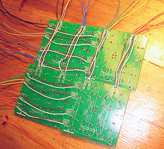
| Sparkfun Button Pad PCBs | 4 | 25.33 EUR |
| Diode Small Signal - 1N4148 | 70 | 6.68 EUR |
| Shipping of Sparkfun order | 1 | 35 EUR |
| Yellow LEDs (3mm, 1000 mcd, shipping included) | 70 | 11.35 EUR |
| Shift register 74HCT165 (Parallel in/serial out) | 1 | 0.95 EUR |
| Shift register 74HCT164 (Serial in/parallel out) | 1 | 0.95 EUR |
| MAX7219CNG+ (LED driver) | 1 | 18.19 EUR |
| 10Kohm, 10 pin, Resistor network | 1 | 0.23 |
| 0.1uf Capacitor | 3 | |
| 10uf Capacitor | 1 | |
| 16 pin IC Socket | 1 | |
| 14 pin IC Socket | 1 | |
| 24 pin IC Socket | 1 | 1.79 EUR |
| Arduino Shield PCB (files, 4pcb) | 1 | 22.78 EUR |
| MachineCollective Enclosure | 1 | 80 EUR |